Discrete ADC Kit: Difference between revisions
From Knox Makers Wiki
Created page with "thumb == Description == The Knox Makers Logo Badge educational electronics kit (KM-001) features six self-flashing LEDs and is powered by a CR2032..." |
No edit summary |
||
| (9 intermediate revisions by the same user not shown) | |||
| Line 1: | Line 1: | ||
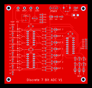
[[File:KM- | [[File:KM-005-board.png|thumb]] | ||
== Description == | == Description == | ||
| Line 13: | Line 12: | ||
| 1 || printed circuit board || - | | 1 || printed circuit board || - | ||
|- | |- | ||
| 1 || | | 1 || USB Jack || - | ||
|- | |||
| 3 || 0.1uF capacitors || C1-C3 | |||
|- | |||
| 11 || LEDs, 5mm or 3mm || D1-D10, D12 | |||
|- | |||
| 34 || 4.7k resistors || R1-R34 | |||
|- | |||
| 1 || Potentiometer, 1M || R35 | |||
|- | |||
| 1 || Switch, SPDT || SW1 | |||
|- | |- | ||
| | | 2 || LM339 quad comparator || U1, U2 | ||
|- | |- | ||
| | | 1 || L74HC148 encoder || U4 | ||
|- | |- | ||
| | | 1 || LM4030BCD 4.096V reference || U4 | ||
|} | |} | ||
== Instructions == | == Instructions == | ||
[ | [Coming soon: PDF via Github]<br> | ||
[Coming soon: Build Video] | |||
== Design == | == Design == | ||
[https://github.com/KnoxMakers/Electronics/tree/master/Solder%20Kits/km- | [[https://github.com/KnoxMakers/Electronics/tree/master/Solder%20Kits/km-005%20discrete%20adc schematic and board layout (Kicad), Gerber files] | ||
== See Other Kits == | == See Other Kits == | ||
[[Electronics]] | [[Electronics]] | ||
Latest revision as of 05:24, 7 October 2022

Description
The Knox Makers Logo Badge educational electronics kit (KM-001) features six self-flashing LEDs and is powered by a CR2032 coin cell battery. Through-hole construction and low parts density make this kit ideal for the soldering novice.
Parts List
| Qty | Part | Designator(s) |
|---|---|---|
| 1 | printed circuit board | - |
| 1 | USB Jack | - |
| 3 | 0.1uF capacitors | C1-C3 |
| 11 | LEDs, 5mm or 3mm | D1-D10, D12 |
| 34 | 4.7k resistors | R1-R34 |
| 1 | Potentiometer, 1M | R35 |
| 1 | Switch, SPDT | SW1 |
| 2 | LM339 quad comparator | U1, U2 |
| 1 | L74HC148 encoder | U4 |
| 1 | LM4030BCD 4.096V reference | U4 |
Instructions
[Coming soon: PDF via Github]
[Coming soon: Build Video]
Design
[schematic and board layout (Kicad), Gerber files
